![]()
![]()
|
|
|
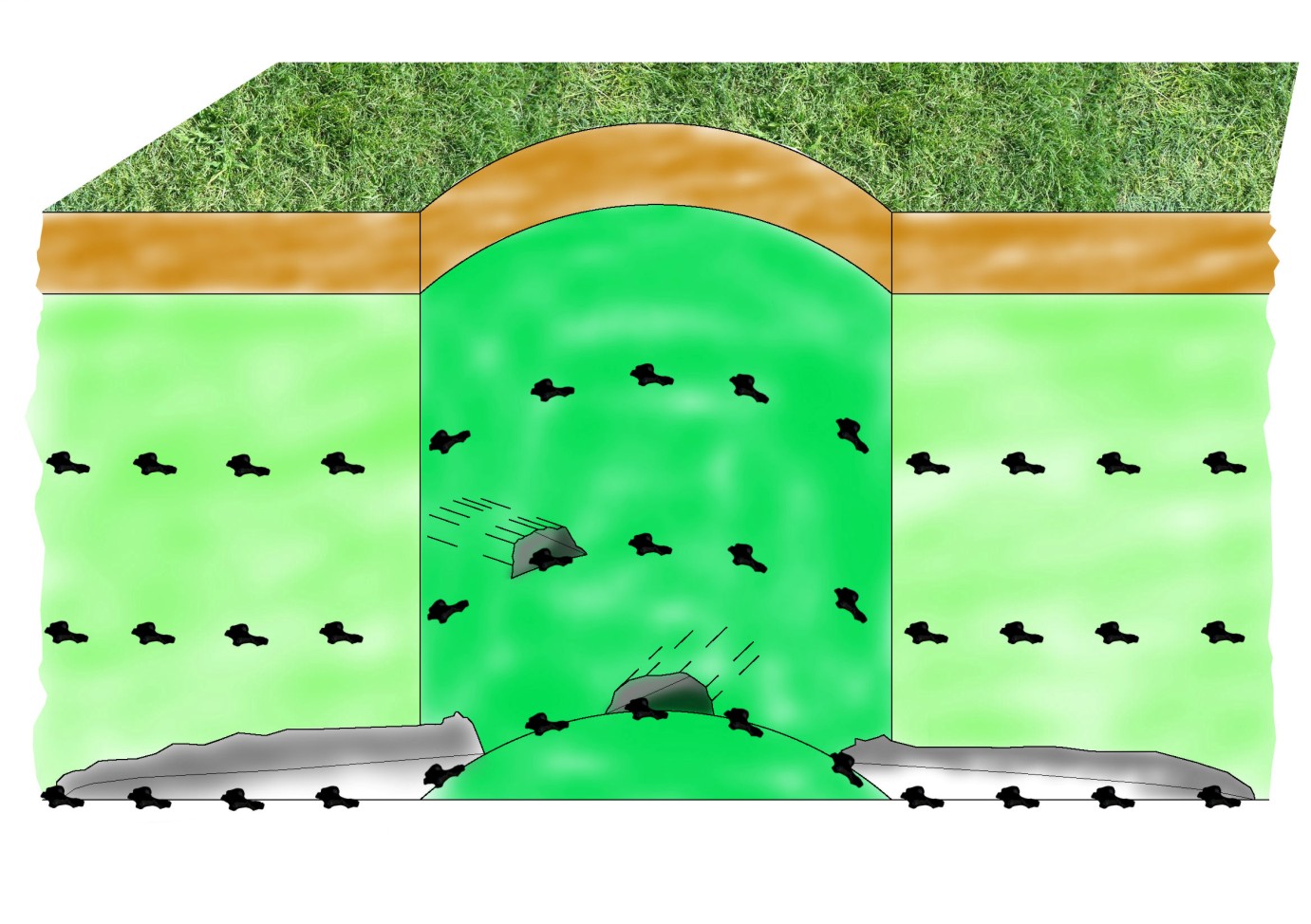
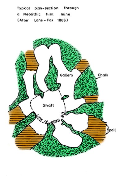
Subsidence Index | Chalk Mining Index | Diagnostic Characteristics | Geographic Occurrence | Investigation & Mitigation | Key Contacts & Expert Advice | Photo Gallery | Essential References & Further Reading | Definitions & Glossary | Flint mine workings Flint mine workings date from two distinct periods of time – the Neolithic and the mid 19th century to the late 1930s. (a) Neolithic flint mines The Neolithic mines have been dated by archaeological investigations (Mason 1978). The miners used deer antlers (as picks), hammer stones and scapulas (as shovels) to create the excavations. The mine workings took the form of large diameter shafts (up to 20m across) and irregular tunnels were dug outwards from the shaft (circa 1m high, up to 2m wide and usually <10m in length) to extract fine quality flints from the flint seams and bands exposed in the sides of the shaft. The flints were then knapped and shaped to produce flint tools and weapons. The number of shafts dug was often large (e.g. 254 shafts at Grimes Graves, Norfolk) and could cover large areas. A typical plan view and cross-section through a Neolithic flint mine is shown as Figure below:
Neolithic flint mine – schematic cross-section. (Image source: Peter Brett Associates)
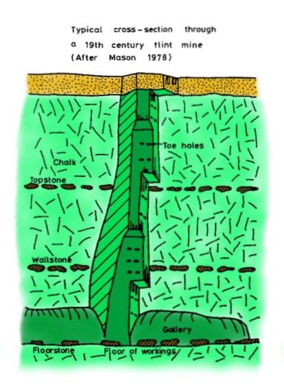
Neolithic flint mine – schematic plan section. (Image source: Peter Brett Associates) (b) Modern flint mines The modern flint mines were dug using a spade, pick and heavy hammer (Mason 1978). Initially a rectangular shaft (about 3m x 1m) was dug through the superficial deposits to reach the chalk. The shaft was continued down into the chalk in a reduced size (about 1m x 1m) and stepped with levels form a crude stairwell, to permit the miner to climb up and down the shaft, while also removing the loads of extracted flint. The final shaft was inclined steeply at about 80 degrees to the vertical. A typical cross-section is shown in Figure below. Low level tunnels (about 1m high) were dug outwards from the shaft to extract the flints contained in the chalk. The best quality flints extracted were knapped or flaked to produce gun-flints for flintlock muskets and pistols, especially during the Napoleonic wars. Lesser quality flints were used for building and road making.
Modern flint mine – schematic cross-section. (Image source: Peter Brett Associates) Chalk mine workings Chalk mine workings also have quite a long history, possibly from Roman times onwards. Mining styles show regional variation and both simple and more complex mine forms appear to co-exist through time. Chalk occurs widely and has been extracted by surface quarrying as well as by mining. In understanding the reasons for carrying out chalk mining it needs to be realised that historically, labour was available and cheap on farms and estates, plus carrying and moving heavy loads of chalk by horse-drawn wagons along poor quality tracks for any distance was difficult, particularly in wet weather. Therefore, it was more convenient to obtain chalk from depth by means of mining at the point where it was needed rather than to obtain it from a distant source. The main uses of mined chalk included:
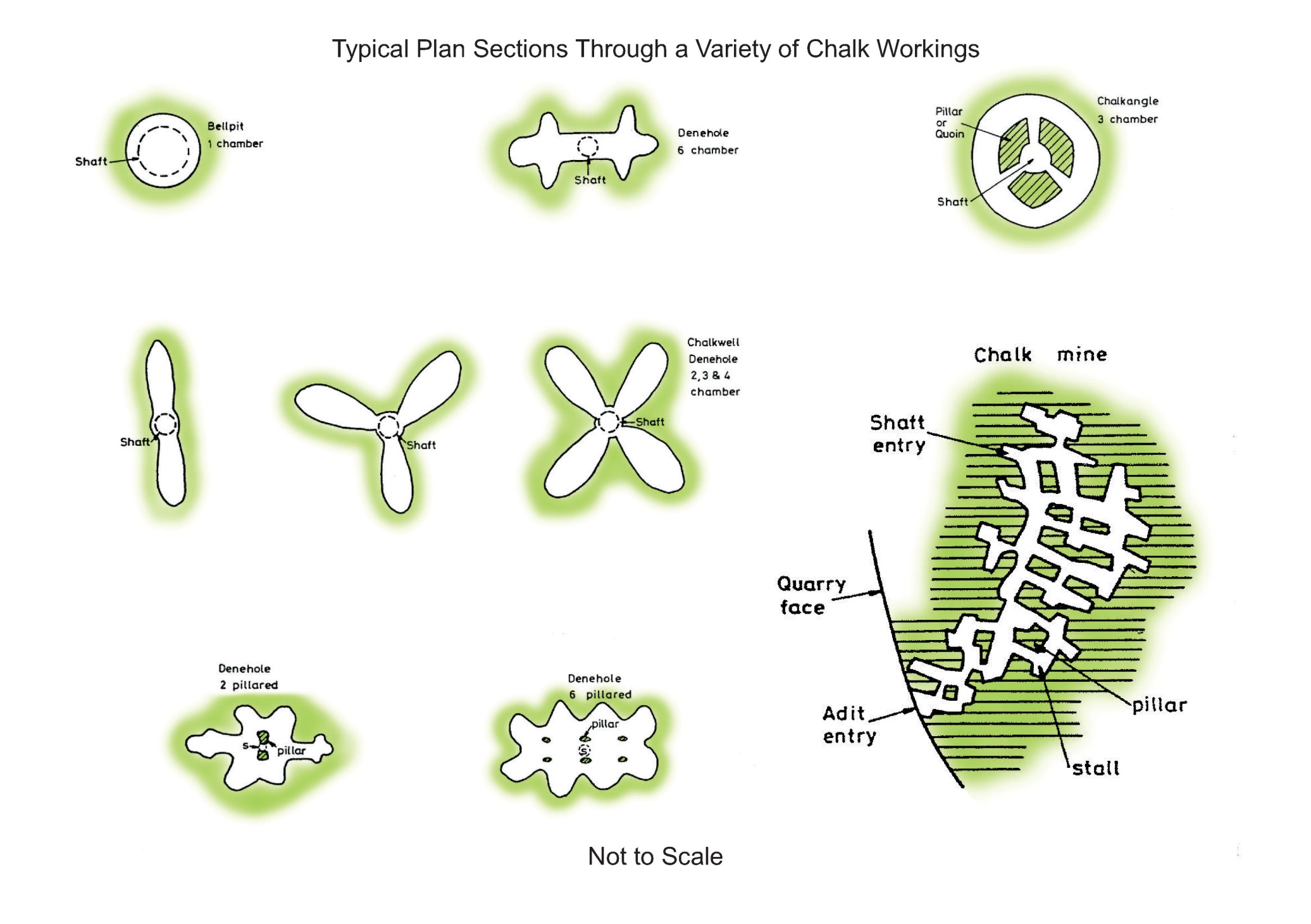
(a) Bellpits Sinking a shaft down through superficial deposits into unweathered chalk at depth and forming a bell-shaped chamber at the shaft base is the simplest form of mining (see figure below). It is probably the oldest form of mining but the style has also continued through to more recent times as well (e.g. Elliott 1887). (b) Deneholes Deneholes are another ancient form of chalk mine, recorded from Roman times onwards, the most accurately dated ones being contemporary with earthworks in northwest Kent, considered to be from the first half of the 13th century (Caiger 1953, 1964, Spurrell 1881, Tester & Caiger 1958). The most commonly occurring deneholes comprise a 1m diameter shaft dug down into fresh chalk, opened out at the shaft base, initially as two tunnels on opposite sides. A pair of short-length tunnels was then formed on either side of the initial tunnel. This style of mine, having double sets of three chambers (trefoils) on each side of the shaft is referred to as a double trefoil type of denehole. Later, more complex forms of pillared deneholes (see Figure 3) were developed as mining skills improved (Spurrell 1881, 1882, Le Gear 1976). A common feature of deneholes is that they are relatively compact (do not normally extend beyond 15m radius from the shaft) and that the tunnels are carefully formed, having a smooth finish to the walls and roof.
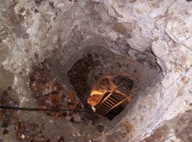
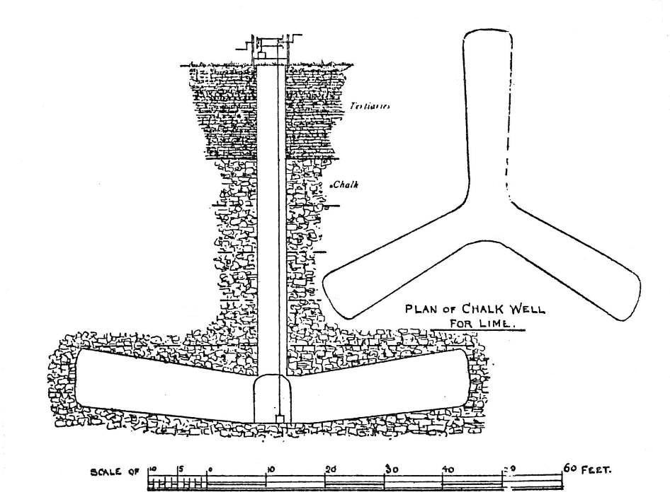
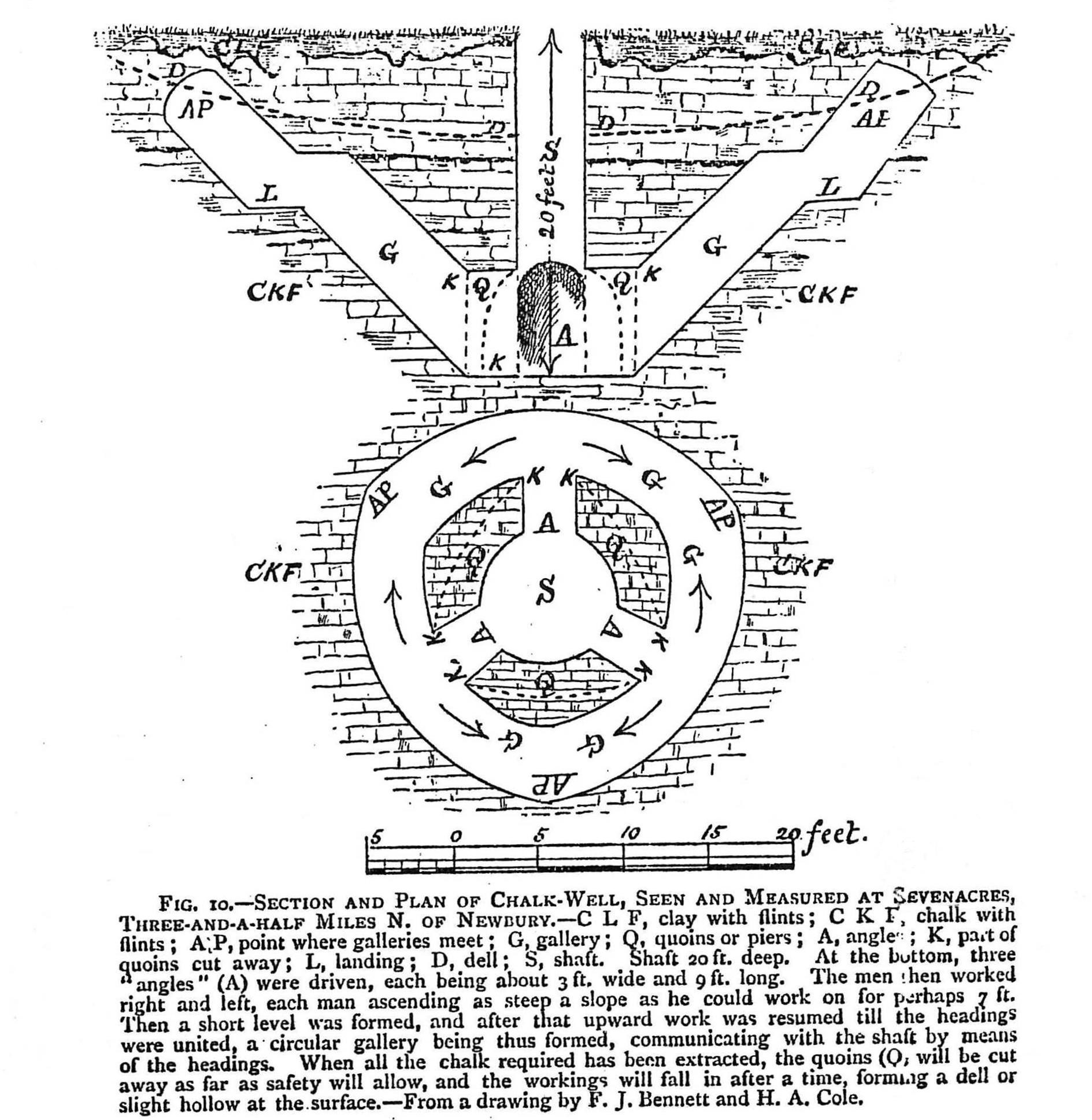
Typical schematic plan sections through a variety of chalk mine workings. (Image Source: Edmonds et al 1990) (c) Chalkwells Chalkwells mainly date from the 1700s and 1800s, though some were dug as recently as the early 1900s. Shaft diameters typically vary from 1.5m to 3m and were dug down through superficial deposits into the underlying unweathered chalk. Anything from two to four tunnels were excavated radially outwards from the shaft base (see Figure 3), often the tunnel floors were inclined towards the shaft and increased in both height and width away from the shaft. The design was to assist with movement of mined chalk towards the shaft from where it was hauled up to the surface by windlass. In some instances the base of the shaft was tapered or belled out. The mining process and agricultural use of the chalk is described in detail by Young (1804). The tunnels created could be 3m or more wide, 3m or more high and extend radially for up to 20m or more. A detailed plan and section through a typical chalkwell prepared by Bennett (1887) is reproduced in the photo gallery section. Mine entry shaft, South Oxhey, Hertfordshire. (Image source: Peter Brett Associates) (d) Chalkangles Chalkangles date from the 1800s and represent a localised variant of the chalkwell. In this case (Bennett 1887, Money 1906) a shaft about 1.5m in diameter is dug through the cover of superficial deposits down into the unweathered chalk at depth. Three or four horizontal tunnels are then driven radially outwards from the shaft base for a short distance before “angling” begins. Angling consists of digging upwards at a steep angle for a distance before establishing a level platform above the shaft floor level. At the new platform level a second set of angles were then dug upwards in opposing directions until they met with the angles being dug from adjacent platforms. These second sets of angles therefore became inter-linked with the adjacent angles to create a ring-shaped pattern (see Figure 3). The steeply constructed angles allowed the mined chalk to fall to the floor level at the base of the angle where it was collected into boxes for hauling to the surface. Finally, on completion of chalk extraction, the pillars (quoins) located between the initially dug horizontal tunnels at the shaft floor level were dug away purposefully to destabilise the mine working. The aim was for the mine to gradually collapse to form a shallow dell at the surface. A detailed plan and section through a typical chalkangle taken from Bennett (1887) is reproduced in the photo gallery section.
(e) Pillar-and-stall mines These larger scale mines appear to date mainly from the early 1800s through to the early 1900s. The shaft or adit entry mines were often located below surface clay pits and associated building complexes that were purpose-built for the mass production of bricks, tiles and pottery ware. Permanent kiln structures were built to fire the bricks, tiles and pottery and also lime kilns operated. These sites were continuously worked for tens of years and hence the demand and volumes of chalk removed underground by mining was much greater.
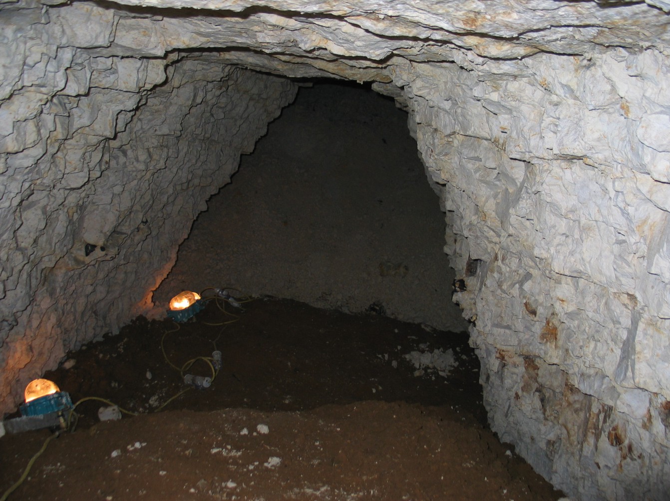
Chalk mine workings, Merton Road, Norwich. (Image source: Peter Brett Associates)
The mines tended to comprise an irregular network of inter-linked tunnels (see Figure 3), though the efficiency of extraction varied, hence some mines have larger or smaller size pillars to support the mine roof than others. Tunnels were typically 2m to 5m wide and could be between 5m and 10m high or more. Mined chalk was often moved by wheelbarrows from the worked face to the working shaft for hauling to the surface. These larger mines often had a secondary shaft created for ventilation. For practical purposes it seems that mines did not generally extend more than 100m from the working shaft position, otherwise the underground movement of mined chalk became too onerous.
Plan and section through a chalkwell. (Image source: Bennett, 1887)
Plan and section through a chalkangle. (Image source: Bennett, 1887)
Subsidence Index | Chalk Mining Index | Diagnostic Characteristics | Geographic Occurrence | Investigation & Mitigation | Key Contacts & Expert Advice | Photo Gallery | Essential References & Further Reading | Definitions & Glossary | |
|